Simnet Basics
18 Aug 2019
In my last post I wrote about resurrecting simnet, but I didn’t describe how to use it. While Joerg’s post gives quite an in-depth example of how one can simulate a large network with simnet, it might be a bit much for someone to handle in one sitting. As a supplement to his post, I thought it would be fun to focus on just the basics of simnet.
Before I delve in, I want to remind you that simnet is a testing tool. There’s probably little reason for an administrator to reach for this in the field. The main user of simnet is most certainly the developer. Either the developer who wants to test some networking changes without the headache of real hardware, or the one who wants to add some automated testing to the networking stack. It’s also useful for the curious person who wants to tinker with the operating system. There’s no wrong usage, per se, but I wanted to set expectations.
Simnet is just another NIC — that’s the key to its power. When building a real, physical network we have three main components: NICs, switches, and routers. Yes, there is much more that can go into a network, but these are the three cornerstones of a typical network. The NICs send and receive frames on behalf of the operating system. The switches connect NICs to form Layer 2 segments. And the routers connect these segments by way of Layer 3 routing. In illumos-based operating systems, like SmartOS, we have a software implementation of each of these. Software routing is handled by enabling IP forwarding, links can be switched with bridges, and NICs can be conjured out of thin air with simnet. If we didn’t have simnet we could still use the other two to do some interesting things, but anything complicated would be hampered by the realities of setting up real NICs. This is what makes simnet such a liberating tool. I’m going to focus solely on simnet in this post and leave bridges and routers for a future one.
Okay, so what’s the most basic thing you could do with a NIC? Hook it up to another one! This is called back-to-back as it involves taking a short cable and running it from the back of one NIC directly to the back of another. This is almost always going to be a completely useless configuration in any production environment, but it can be very useful to a developer like myself when running tests. It also happens to be the only way you can use a simnet device: each simnet device can only be connected directly to another one [1]. Here’s what it looks like.
# dladm create-simnet faux1
# dladm create-simnet faux2

# dladm show-simnet
LINK        MEDIA               MACADDRESS        OTHERLINK
faux1       Ethernet            66:e6:1:46:80:16  --
faux2       Ethernet            5e:ce:22:91:1c:5a --

# dladm modify-simnet -p faux2 faux1

# dladm show-simnet
LINK        MEDIA               MACADDRESS        OTHERLINK
faux1       Ethernet            66:e6:1:46:80:16  faux2
faux2       Ethernet            5e:ce:22:91:1c:5a faux1
And here is the usage for the two commands, taken from the PSARC case.
    create-simnet [-t] [-m <media>>] <link>
        A new simnet device is created on the system with the given
        linkname. Media can either be Ethernet (default) or WiFi.

    modify-simnet [-t] [-p <peer>] <link>
        Another simnet is associated as the peer link of an existing
        simnet. If the -p option is not specified any existing peer
        link associated with the simnet instance is removed.
Basically, the three commands above are equivalent to inserting two single-port Ethernet cards into the motherboard and running a cable directly between the two.
As I said before, as far as the operating system is concerned, these are no different from real NICs. Just like real hardware, we can create VNICs, add IP interfaces, and send and sniff traffic across the interfaces.
# dladm create-vnic -t -l faux1 ryan1
# dladm create-vnic -t -l faux2 ryan2

# dladm show-vnic ryan1
LINK         OVER       SPEED MACADDRESS        MACADDRTYPE VID  ZONE
ryan1        faux1      100   2:8:20:63:c:54    random      0    --

# dladm show-vnic ryan2
LINK         OVER       SPEED MACADDRESS        MACADDRTYPE VID  ZONE
ryan2        faux2      100   2:8:20:69:a4:6d   random      0    --

# ipadm create-addr -t -T static -a 192.168.7.10/24 ryan1/v4
# ipadm create-addr -t -T static -a 192.168.7.11/24 ryan2/v4

# ipadm show-addr
ADDROBJ           TYPE     STATE        ADDR
lo0/v4            static   ok           127.0.0.1/8
igb0/_a           static   ok           192.168.2.3/24
ryan1/v4          static   ok           192.168.7.10/24
ryan2/v4          static   ok           192.168.7.11/24
lo0/v6            static   ok           ::1/128

# ping -s -i 192.168.7.10 192.168.7.11 56 3
PING 192.168.7.11: 56 data bytes
64 bytes from 192.168.7.11: icmp_seq=0. time=0.197 ms
64 bytes from 192.168.7.11: icmp_seq=1. time=0.095 ms
64 bytes from 192.168.7.11: icmp_seq=2. time=0.057 ms

----192.168.7.11 PING Statistics----
3 packets transmitted, 3 packets received, 0% packet loss
round-trip (ms)  min/avg/max/stddev = 0.057/0.116/0.197/0.072
In the previous commands I created VNICs and IP objects over
each of the simnet links. Then I sent pings between the
interfaces. Next, I'll snoop the faux1 link while
running a ping.
# snoop -v -d faux1
Using device faux1 (promiscuous mode)
ETHER:  ----- Ether Header -----
ETHER:
ETHER:  Packet 1 arrived at 19:44:48.45647
ETHER:  Packet size = 98 bytes
ETHER:  Destination = 2:8:20:69:a4:6d,
ETHER:  Source      = 2:8:20:63:c:54,
ETHER:  Ethertype = 0800 (IP)
ETHER:
IP:   ----- IP Header -----
IP:
IP:   Version = 4
IP:   Header length = 20 bytes
IP:   Type of service = 0x00
IP:         xxx. .... = 0 (precedence)
IP:         ...0 .... = normal delay
IP:         .... 0... = normal throughput
IP:         .... .0.. = normal reliability
IP:         .... ..0. = not ECN capable transport
IP:         .... ...0 = no ECN congestion experienced
IP:   Total length = 84 bytes
IP:   Identification = 60954
IP:   Flags = 0x4
IP:         .1.. .... = do not fragment
IP:         ..0. .... = last fragment
IP:   Fragment offset = 0 bytes
IP:   Time to live = 255 seconds/hops
IP:   Protocol = 1 (ICMP)
IP:   Header checksum = fe27
IP:   Source address = 192.168.7.10, 192.168.7.10
IP:   Destination address = 192.168.7.11, 192.168.7.11
IP:   No options
IP:
ICMP:  ----- ICMP Header -----
ICMP:
ICMP:  Type = 8 (Echo request)
ICMP:  Code = 0 (ID: 34262 Sequence number: 0)
ICMP:  Checksum = 7f27
ICMP:

ETHER:  ----- Ether Header -----
ETHER:
ETHER:  Packet 2 arrived at 19:44:48.45654
ETHER:  Packet size = 98 bytes
ETHER:  Destination = 2:8:20:63:c:54,
ETHER:  Source      = 2:8:20:69:a4:6d,
ETHER:  Ethertype = 0800 (IP)
ETHER:
IP:   ----- IP Header -----
IP:
IP:   Version = 4
IP:   Header length = 20 bytes
IP:   Type of service = 0x00
IP:         xxx. .... = 0 (precedence)
IP:         ...0 .... = normal delay
IP:         .... 0... = normal throughput
IP:         .... .0.. = normal reliability
IP:         .... ..0. = not ECN capable transport
IP:         .... ...0 = no ECN congestion experienced
IP:   Total length = 84 bytes
IP:   Identification = 34300
IP:   Flags = 0x4
IP:         .1.. .... = do not fragment
IP:         ..0. .... = last fragment
IP:   Fragment offset = 0 bytes
IP:   Time to live = 255 seconds/hops
IP:   Protocol = 1 (ICMP)
IP:   Header checksum = 6646
IP:   Source address = 192.168.7.11, 192.168.7.11
IP:   Destination address = 192.168.7.10, 192.168.7.10
IP:   No options
IP:
ICMP:  ----- ICMP Header -----
ICMP:
ICMP:  Type = 0 (Echo reply)
ICMP:  Code = 0 (ID: 34262 Sequence number: 0)
ICMP:  Checksum = 8727
ICMP:
Next I’d like to show off the hardware offload features I added, but first I’ll run some TCP/IP traffic without them and verify the stream in Wireshark. To do this I’ll use the netcat and snoop commands.
Start the server.
# nc -l 192.168.7.11 9999
Start snooping the faux1 (sender) interface.
# snoop -v -d faux1 -o /var/tmp/hello-no-offloads.pcap
Using device faux1 (promiscuous mode)
Connect to server and send message.
# nc -s 192.168.7.10 192.168.7.11 9999
hello
^D
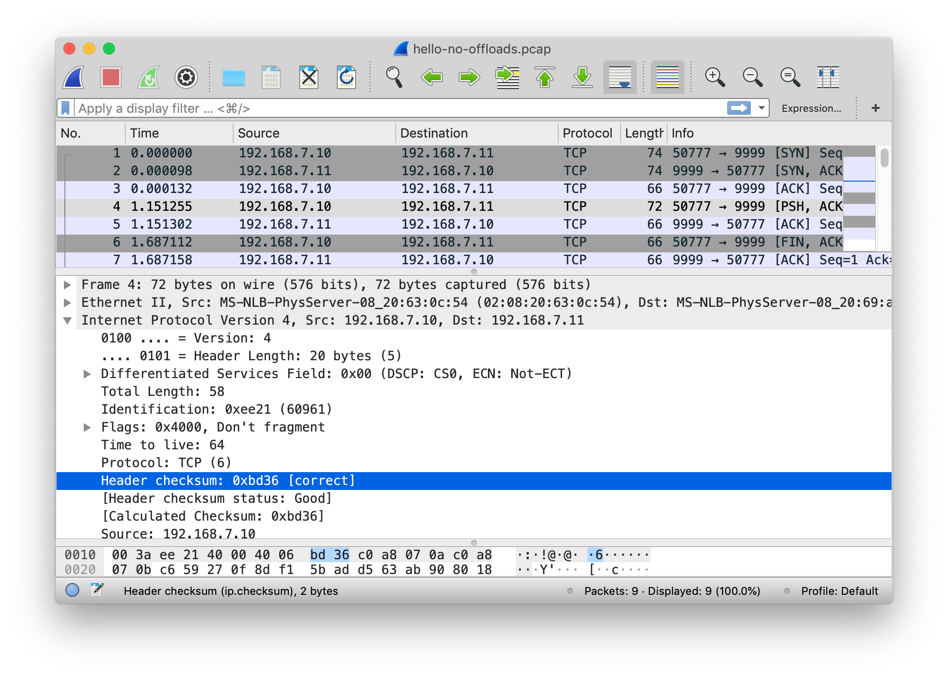
Copy the resulting packet capture and open it up in Wireshark.
In my screenshot below I highlight the IP header checksum
field of the first data packet (Frame 4). Notice that the
header checksum is marked [correct]. I asked
Wireshark to verify IP checksums and this tag is the result of
such verification [2].
By default, the simnet device will assume no offload capabilities. But what fun is that? By setting private properties on the link we can enable the various capabilities. Here is the list of private properties currently available.
_tx_ipv4_cksum=off|on- Enable IPv4 header checksum offload.
_tx_ulp_cksum=none|partial|fullv4- Enable ULP (Upper Layer Protocol, such as TCP/UDP) checksum offload. Partial offload is when the network stack calculates the pseudo header checksum but the NIC does the rest. Full is when the NIC calculates the entire checksum. We only offer full offload for IPv4 at the moment because none of the offload negotiation logic is wired up for IPv6.
_lso=off|on- Enable Large Send Offload (LSO). This will allow the IP stack to send 64K byte packets all the way down to the NIC.
Let’s test the TCP/IP Tx checksum offloads by setting the properties and using Wireshark to verify the checksum value is zero.
# dladm set-linkprop -p _tx_ipv4_cksum=on faux1
# dladm show-linkprop -p _tx_ipv4_cksum faux1
LINK         PROPERTY        PERM VALUE          DEFAULT        POSSIBLE
faux1        _tx_ipv4_cksum  rw   on             off            --

# dladm set-linkprop -p _tx_ulp_cksum=fullv4 faux1
# dladm show-linkprop -p _tx_ulp_cksum faux1
LINK         PROPERTY        PERM VALUE          DEFAULT        POSSIBLE
faux1        _tx_ulp_cksum   rw   fullv4         none           --

# dladm create-vnic -t -l faux1 ryan3
# dladm show-vnic ryan3
LINK         OVER       SPEED MACADDRESS        MACADDRTYPE VID  ZONE
ryan3        faux1      100   2:8:20:9b:1a:72   random      0    --

# ipadm create-addr -t -T static -a 192.168.7.12/24 ryan3/v4
# ipadm show-addr
ADDROBJ           TYPE     STATE        ADDR
lo0/v4            static   ok           127.0.0.1/8
igb0/_a           static   ok           192.168.2.3/24
ryan1/v4          static   ok           192.168.7.10/24
ryan2/v4          static   ok           192.168.7.11/24
ryan3/v4          static   ok           192.168.7.12/24
lo0/v6            static   ok           ::1/128
In order for IP to pick up the new capabilities I had to
create a new VNIC (ryan3) on top
of faux1. When you set one of these properties on
simnet it will renegotiate capabilities with its clients, but
for some reason this doesn’t make it past the VNIC —
something to explore another day. Running the same netcat test
as before, but this time sending from the
checksum-offload-capable 192.168.7.12, I get the
following packet capture.
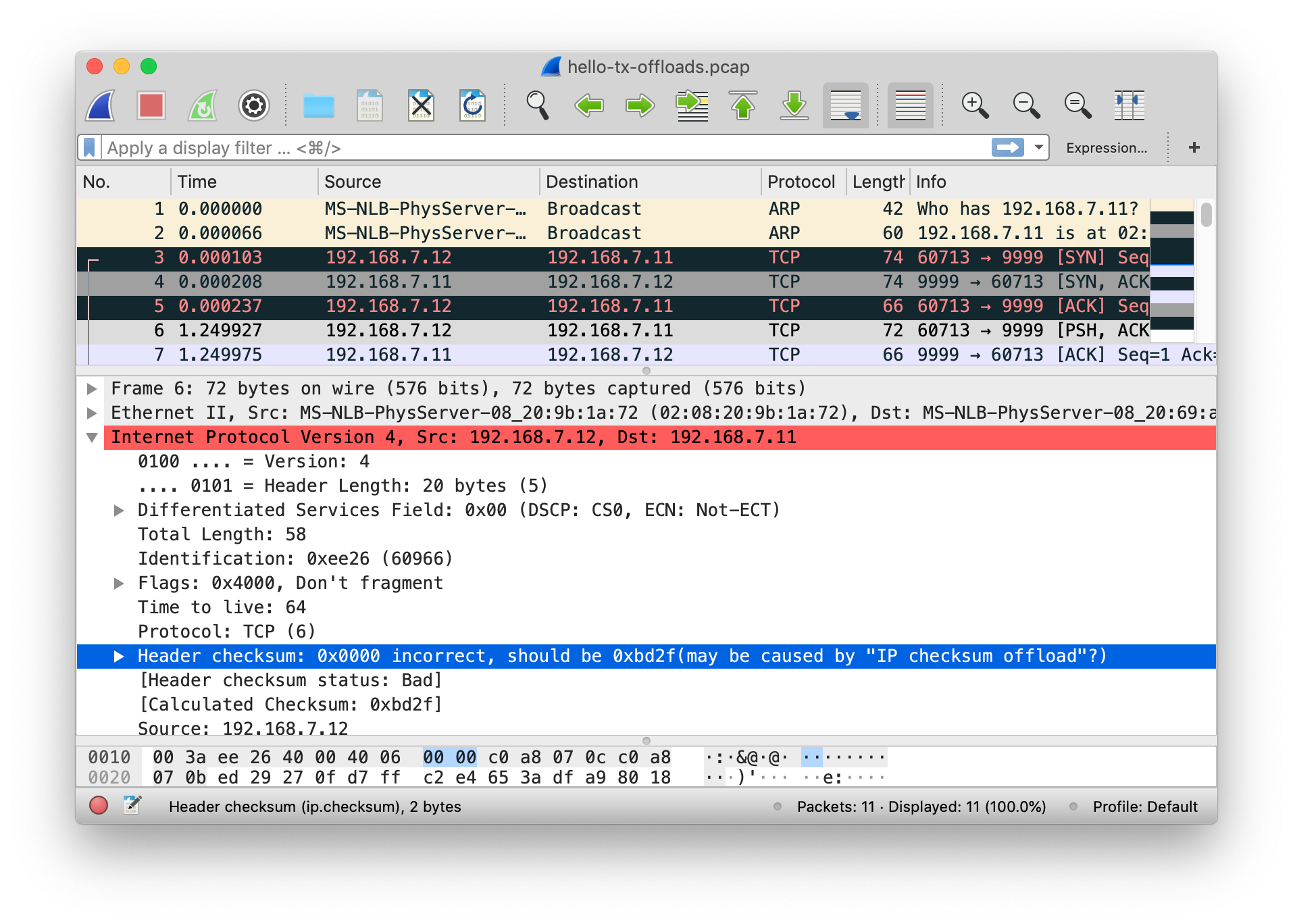
As expected, Wireshark marks the IP header checksum
as incorrect since it contains a value of zero.
That’s because the checksum calculation will now be done
inside of the simnet device as it would be for a real NIC; and
the snoop mechanism intercepts the
packets before they reach the device. This also
explains why you’ll typically see missing Tx checksums when
using snoop or tcpdump on your real hardware — because almost
all hardware provides these offloads.
That’s pretty much all there is to simnet. To start building bigger networks you need to bring in bridges and routers. I’ll leave that for a follow up post (hopefully soon).
-
You might wonder: if you can only connect simnet devices in a back-to-back manner, how do you create LAN segments? As I hinted at, you use a bridge (
dladm
	    create-bridge
) to switch packets between networking devices. This is a bit confusing because in the physical world you would use a cable to link the port of the NIC to the port of the switch. But in the simnet world the port of one simnet is connected directly to the port of another — so it would seem impossible to ever create L2 segments. However, the bridge is implemented in software and doesn’t need to emulate the physical world exactly. Instead, the bridge code inserts itself at a very low level of the mac module in order to know when an Ethernet frame should be forwarded from one device to another. - Wireshark checksum verification